


Robert D. Ricklefs Great Western Manufacturing
Because a sifter rotates, vibrates, gyrates, or reciprocates at high speed, it is subject to high levels of mechanical stress. You can keep your sifter in top shape by regularly inspecting and servicing it. Find out how to do that in this article, which expands on sifter information the author covered in his previous article “Selecting a sifter for scalping, removing fines, or grading”.
To perform up to your expectations, a sifter (also called a screener) must provide sharp size separations and consistent discharge to your downstream process. But this kind of sifting performance will not happen if you do not pay regular attention to how your sifter is behaving — what is going into it, what is coming out, and how the sifter looks and sounds.
A few sifter basics
A sifter mechanically separates a dry free-flowing material according to particle size by moving the material in relation to a screen. The sifter can be applied to scalp, grade, or remove fines from the material. Scalping removes over-size; grading classifies the material through a coarse screen and over a fine screen and can simultaneously pro-duce multiple intermediate sizes; and removing fines separates the fine particles from the final product.
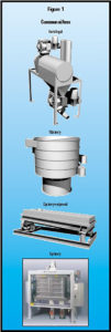
Four sifter types — centrifugal, vibratory, gyratory-reciprocal, and gyratory, as shown in Figure 1 — are common. Each has different components and produces a different type of sifting motion to separate the material. Your sifter’s components, including the screen (its type, mesh size, open area, attachment method, and tension) and screen cleaners (for vibratory, gyratory-reciprocal, and gyratory sifters), must match your material’s characteristics to provide good sifting performance. [Editor’s note: Find more detail in sources listed in the later section “For further reading.”]
In a manufacturing process, the destinations for the sifter’s size separations vary widely. Typically, the oversize material is ground further and then resifted. On-size material (the final product) can undergo further processing or proceed to packaging. Removed fines are commonly a by-product, but in some cases, they have value as a product or can be processed further and reclaimed for use in another product.
In a quality assurance application, when the sifter is either receiving a raw material or making a final material check before further processing or packaging, the sifter removes oversize (tailings) that are typically collected in a container below the sifter outlet.
 Whether your sifter is applied in processing or quality assurance, monitoring all of its separations can provide important clues about the sifter’s operation and condition and about changes in your raw material or upstream processing and conveying equipment. In a quality assurance application, it is critical to frequently remove the tailings container and inspect the tailings. Carefully examine all tailings in the container to discover contaminants or on-size product, either of which can indicate current or developing problems; never discard unexamined tailings as waste.
Laying the groundwork for good maintenance
Effective maintenance for any type of sifter is based on these elements: properly locating the sifter, training workers, and developing a maintenance inspection schedule and checklist.
Sifter location: Install the sifter in an area that provides easy access for the workers who regularly inspect the sifter and for the maintenance workers who service it. A floor-level location is not only easiest and safest for your workers, preventing them from having to climb ladders and platforms, but will help ensure that workers inspect and service the sifter more regularly. Make sure that there’s ad-equate space around the machine to enable workers to easily inspect the sifter’s mechanical parts, including the drive mechanism, and easily remove and replace the screens, which can be quite large. Easy access to the dis-charge outlets (which typically are equipped with inspection ports) or to the tailings container helps workers analyze the separations for signs of problems with the raw material, the sifter, or upstream equipment.
Worker training: Train your inspection and maintenance workers to know which sifter components to inspect, how to perform preventive maintenance, and how to repair or replace worn or damaged components on the unit. With good training, they will be able to notice component wear and unusual operating noises before the sifter slows or stops running or your product quality drops.
Establish and maintain a regular sifter inspection schedule.
Maintenance inspection schedule and checklist: The inspection frequency will depend on various factors, including your sifter’s application (quality assurance or processing) and the material it handles. For instance, you may choose to inspect a sifter at the raw material receiving point after each bulk load, while a sifter in a processing ap-plication may dictate regular, even round-the-clock inspections to catch problems before product quality is affected. More frequent inspections are required when faster wear is likely, such as when your sifter operates at high speed or when it handles an abrasive material.
To aid the inspection process, develop a checklist of items to examine during each sifter inspection. Typical listed items are the screens, screen frames, screen cleaners, gaskets between screen decks, drive mechanism, sieve-clamping mechanism, and flexible sleeves connecting the sifter to upstream and downstream equipment. Provide a space after each item on the checklist so workers can initial and date it, thus producing an inspection record for future reference.
Also include a space on the checklist where workers can record problems they have noticed, like material leaks, vibration, and strange sounds, so your maintenance workers can fix the problems the next time they service the unit.
Inspecting your sifter
To ensure that the sifter continues to operate effectively, regularly inspect all items listed on the checklist:
Screens, screen frames, screen cleaners, gaskets, and flexible sleeves: Open the sifter housing and inspect the sifter components. Check the screens, screen frames, screen cleaners, gaskets (or sealing material) between the screen decks, and flexible sleeves for signs of wear. Repair or replace worn parts. Some worn items are obvious, such as gaskets or flexible sleeves that leak material. But be aware that some items can have less-obvious problems that require a closer look. For instance, the screen cleaners may have worn to the point that some have passed through the screen’s backwire (which holds the cleaners against the screen bottom), eventually preventing adequate screen cleaning and resulting in screen blinding.
Drive mechanism and sieve-clamping mechanism: When you inspect the sifter, also inspect the drive mechanism and sieve-clamping mechanism. Depending on the drive type, check for items such as adequate bearing lubrication, adequate motor lubrication, or proper belt tension. Follow the supplier’s recommendations for lubricating the drive mechanism, and repair or replace parts as required. Carefully inspect the sieve-clamping mechanism to ensure that the sieves will be properly secured during operation. Check with the supplier for advice on servicing your sieve-clamping mechanism.
Troubleshooting tips
Problems with your processing or handling equipment, unrelated to sifter performance, often become evident at your sifter and falsely give the impression that the sifter has a problem. The trouble, which can stem from things like poor installation or maintenance of upstream and downstream equipment, can fool you into trying to track down a problem in the wrong equipment. Here are troubleshooting tips for problems evident at the sifter, whether they originate in the sifter itself or elsewhere.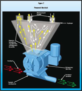
Pneumatic blowback: Pneumatic blowback, as shown in Figure 2, can affect a gravity-flow sifter installed in a pneumatic conveying system when the surge hopper above the discharge rotary airlock valve is not adequately vented. This is particularly evident when the hopper’s static bin vent filter (a sock filter fitted over the air vent) is plugged. The surge hopper’s plugged filter forces the blowback air that exits the airlock valve back up through the sifter’s outlet. The air follows the path of least resistance, blowing on-size product that has discharged through the sifter’s bottom screen back up through the out-let and through the bottom screen, where it will continue to flow out of the sifter as oversize. This can cause you to think the sifter is not removing all of the fines.
To ensure better air relief, you can regularly clean or change the bin vent’s sock filter. However, a better solution is to use an active suction or dust control system that will provide a continuous uniform suction on the surge hopper to relieve the excess air. Depending on your sifter type, other solutions may also be available; contact your sifter supplier for more information on these.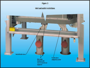
Inlet or outlet restrictions: Restrictions in the sifter inlet and outlets, as shown in Figure 3, are a common sifter problem. Such restrictions can occur when the sifter inlet or outlets are too small for the material flowrate or are blocked by debris; when the flexible sleeves at the inlet or outlets are twisted, misaligned, or collapsed because of high suction; and when the chutes leading to downstream equipment have too shallow an incline to promote the dis-charged material’s gravity flow or have a flattened cross-section resulting from an operator’s attempt to promote flow by hitting the chute with a hammer. A restricted inlet causes material to back up, making it look like the sifter cannot handle the feedrate. A restricted outlet causes on-size product to back up and flow out with the tailings, which can lead you to think the screen area is not adequate or the mesh size is too small.
Take appropriate actions to eliminate these restrictions. Replace each undersized sifter inlet or outlet with a properly sized inlet or outlet, screen your raw materials for de-bris, and straighten all flexible sleeves and align them properly with each inlet and outlet (which may require adjusting the location of the sifter or upstream or down-stream equipment). To prevent the connections from collapsing, reduce suction through the sifter or switch to connections reinforced with stiff rings. Also ensure that the chutes leading to downstream equipment are inclined steeply enough to promote gravity flow and protect the chutes from impact damage.
Poor screen tension: A loose screen that has lost its proper tension can cause several problems during sifter operation. Material cannot stratify on the loose screen and instead pools or puddles on it, preventing the material from moving easily across it. This can choke your sifter and halt the downstream process. The loose screen can also keep your screen cleaners from doing a good job. The cleaners are less effective when bouncing against the loose screen, and this can eventually blind the screen and cause on-size product to carry over with the tailings.
How to solve the problem depends on your screen’s attachment type. If the screen is attached to the frame mechanically — with grommets and hooks or looped edges and rods — you can tighten the screen tension yourself. If the screen is bonded with adhesives, in some cases you can send the screen back to the sifter supplier for rescreening or order adhesives and stretching equipment from the sup-plier to do this at your plant. With some bonded screens, you must discard the loose screen and replace it with a new pretensioned screen.
Consult with your sifter supplier to determine which screen cleaner material and shape are best for your application.
Incorrect screen installation: Material can back up when your screens are installed incorrectly — such as when screens are placed out of order in the sifter or when a screen is turned 90 or 180 degrees from its correct orientation. In either case, the sifter may work for a while, but it is likely that the separations will not be correct and the ma-chine will eventually completely fill. Check that the screens are in the correct order, with largest mesh size at the top and smallest at the bottom, and that each screen is properly oriented.
Incorrectly applied or worn screen cleaners: Screen cleaners come in several materials, typically rubber or plastic, and in many shapes. When the screen cleaners in your sifter are not the right material or shape for your application, or when the cleaners are worn, they will not clean the screen effectively. This will cause screen blinding and plugging that sends your on-size product out with the tailings. Pieces or particles worn from the cleaners can also contaminate your material.
Consult with your sifter supplier to determine which screen cleaner material and shape are best for your application. For instance, if your cleaners have quickly worn away, switch to cleaners made of longer-wearing material. If your cleaners are round and the screens have become blinded by sticky material, you can switch to cube cleaners, which do a better job of scraping the screen’s under-side. In some cases, you may need to use a combination of cleaner types or a different quantity of them to keep your screens clean.
Material changes: When you switch materials or your raw material’s characteristics change, the sifter’s performance can degrade. If your sifter handles multiple materials or material grades, you may notice as some materials are sifted that the sifting process has slowed, and that on-size product is exiting with the tailings. This problem can indicate that the screens in your sifter are not suited to sifting the variety of materials fed to it. In this case, you can either replace the screens with new ones selected to handle your worst-case material, or you can keep multiple spare screen sets on hand and change screens for each material.
If your raw material’s characteristics change from bulk load to bulk load, the sifter can also slow and send on-size product out with the tailings. One indicator of raw material changes is a fluctuating feedrate to the sifter. To correct this problem, you may need to provide more stringent quality control checks at the receiving stage and ensure that out-of-spec raw material is either properly conditioned before sifting or is rejected.
Screen changes: Replacing one screen type with another can degrade your sifter’s performance. The screen originally specified for your sifter was matched to your application requirements, with an appropriate type (wire or synthetic), open area, and mesh size. Replacing the original screen with one that has less open area can restrict your sifter, causing on-size product to exit with the tailings. When replacing a screen, avoid choosing a cheaper or more readily available screen. Make sure you select the same screen or consult your sifter supplier to determine which screen suits your application.
Drive speed or sifting motion: Eventually, the sifter’s drive mechanism will fail, requiring you to disassemble it to repair or replace parts. Afterward, you may notice changes in the sifter’s drive speed or sifting motion. Either problem can restrict flow through the sifter and indicates that the drive mechanism was incorrectly reassembled with the wrong parts. Correct the drive speed and sifting motion by reassembling the drive mechanism with parts identical to the original ones.
Rate changes: Equipment problems are often behind changes in the sifter feed and discharge rates. If you notice that the feedrate to the sifter has changed, causing the sifter to become overloaded, look for a feeder change such as worn rotors in a rotary airlock valve or a valve with a new motor or rotor. These can cause the valve to operate at too high a speed. They also can lead to valve leaks and blow-back, preventing the rotor pockets from filling with material and correctly feeding the sifter. If you notice that material is backing up into the sifter from below, look for problems in the discharge rotary airlock valve. Worn rotors or too slow an airlock or conveyor speed will prevent the material from being taken away quickly enough from the outlet. A plugged bin vent filter in the downstream surge hopper can also cause changes in the sifter’s feed and discharge rates. Take steps to correct these problems by repairing the rotary airlock valve with appropriate parts, making conveyor re-pairs, or replacing the bin vent’s sock filter.
For further reading
Find more information on sifters in “Selecting a sifter for scalping, removing fines, or grading” by Robert D. Ricklefs, Powder and Bulk Engineering, December 2000
Robert D. Ricklefs retired as Director of Sales from Great Western Manufacturing with more than 25 years’ experience in cereal and grain processing.
As Published in Powder & Bulk Engineering – 12.01.2002
Copyright 2021, CSC Publishing, Inc. All rights reserved.
